Modelers often find it necessary to edit and adjust a wide range of parameters displayed in the 2DH view of EFDC+Explorer (EE). For example, you may need to decrease bathymetry in a specific area or increase the bottom roughness in another. EE provides flexibility for the modeler by using polygons to specify spatially varying parameters. Apart from bottom elevation and the roughness coefficient, water elevation, and temperature can all be adjusted this way. This blog describes how to do this quickly and easily.
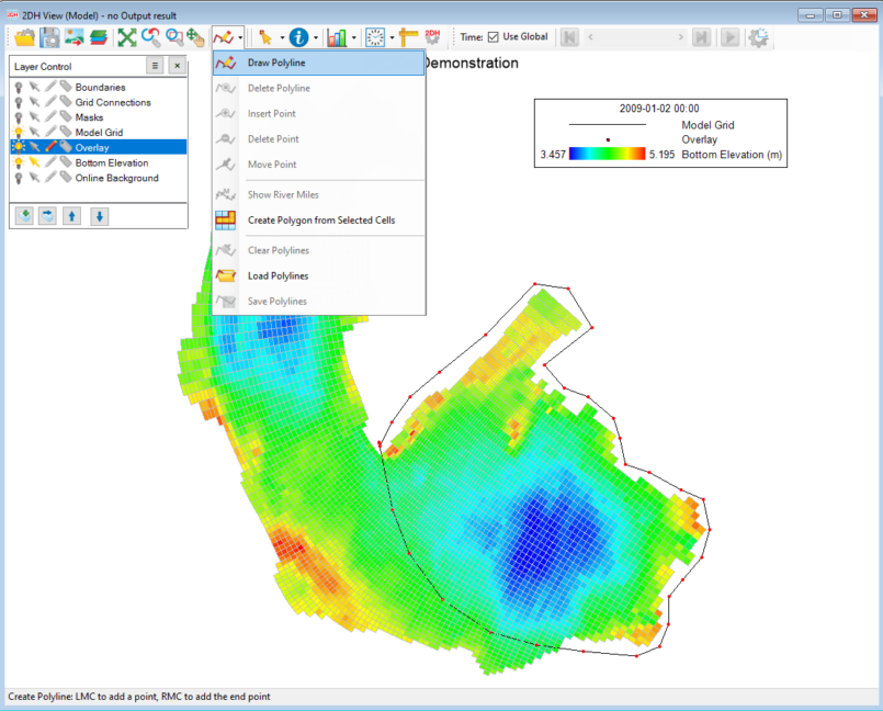
You can load an existing polygon file into EE or draw a new polygon in the 2DH View of EE. The tool used to create a polygon is Draw Polyline in 2DH View as shown in Figure 1.

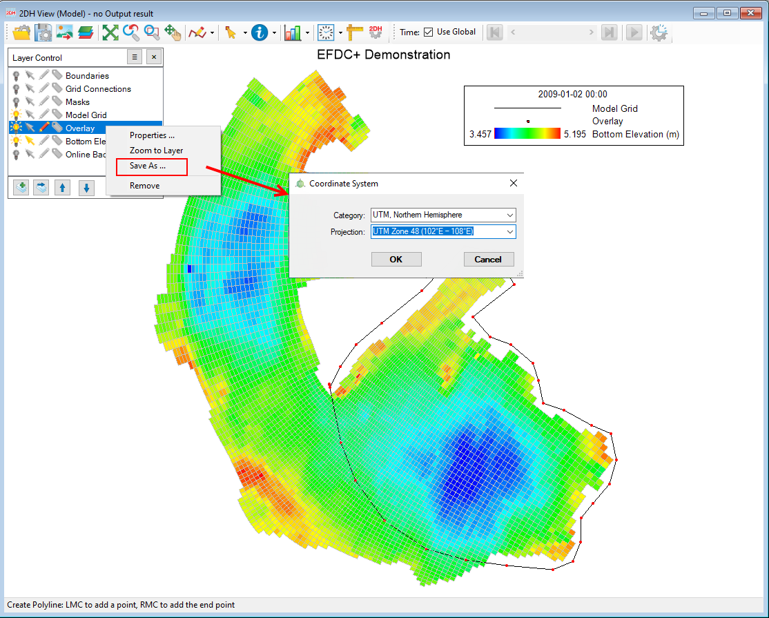
Once you have completed making the outline, the overlay layer can be saved as a polygon file in the _p2d or _.ldb format, as shown in Figure 2. EE allows you to export the polygon file in either the UTM projection zone or geographic coordinate system.

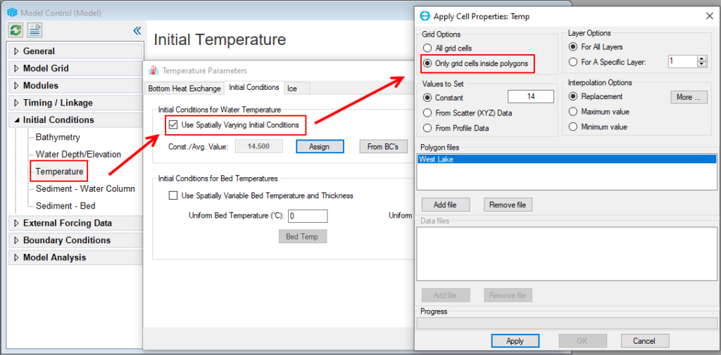
When setting the initial conditions (ICs) in each EFDC+ module, EE provides a user-friendly and intuitive interface for use of a polygon to specify spatially varying parameters. An example of using a polygon to determine spatially varying temperature initial conditions is shown in Figure 3 below. Check the Use Spatially Varying Initial Conditions checkbox in the Temperature Parameters form. The form of Apply Cell Properties: Temp will be displayed.

Use the Grid Options frame to define the number of grid cells of the model domain that you wish to assign for modification. In our case, we want to select the option Only grid cells inside polygons. The polygon file can be in _p2d or _.ldb formats and may contain one or more polygons.
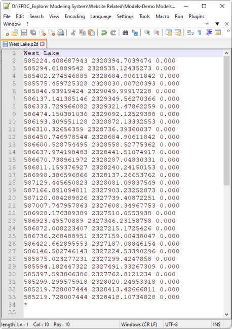
An example of the polygon file is shown in Figure 4. The first line is the “ID” of the polygon. Next comes the data in either 2D or 3D format. The importing process automatically handles either. Finally, the polygon file is finished (not necessarily “closed”) by an “*” in column 1.
You should specify what changes you wish to make to the current value in the Values to Set frame. The simplest option is to set a constant value. Select Constant and enter the value in the text box. Another option is to use From Scatter (XYZ) data which requires uploading measured or otherwise determined data from a file in *.dat format.
The Interpolation Options frame lets you determine how the scatter or profile data will be interpolated. For the replacement option, the current grid cells will be replaced with the value calculated by the interpolation process for that cell. The maximum value option will alter a grid cell only if the newly interpolated data is higher than the current value of that cell. The minimum value option will only alter a grid cell if the newly interpolated data is lower than the current value of that cell.

Using polygons to modify your model is essential in becoming a more efficient user of EEMS. If you don’t have a current EEMS license, you can still try this using EEMS in demo mode. You can download the EEMS software from our website and use your website registration name and password to activate demo mode.


