Equation-based Options in Hydraulic Structures
In our previous blog, we provided an overview of simulating hydraulic structures in EEMS, where we discussed the importance of rating tables and flow lookup tables in determining flow rates based on water surface elevations. Building upon that, we will explore another powerful feature of EEMS: using equations to define the flow-governing properties of hydraulic structures such as culverts, weirs, sluice gates, and orifices, offering engineers and scientists a variety of flow modeling optimization tools.
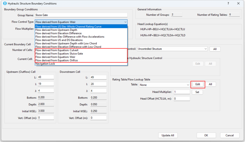
In the Hydraulic Structure Boundary Conditions form, click on the Flow Control Type to display a drop-down menu. Four options determining the flow based on equations are shown, as in Figure 1. Select one of these equations, then click the Edit button to choose the corresponding structure type. Detailed descriptions of all structure types are provided below. For a detailed explanation of the first seven options, which utilize a rating table or flow lookup table, please refer to the first and second blogs in this series.
Culverts
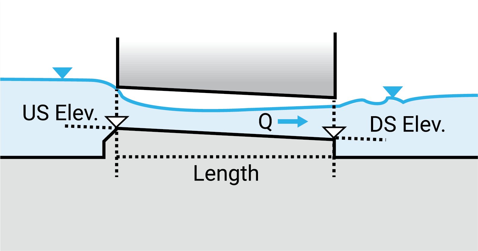
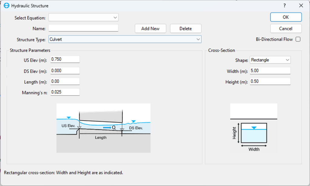
Culverts are crucial in channeling water beneath roads, railways, or barriers. In EEMS, configuring culverts involves setting parameters like upstream and downstream elevations, length, and Manning’s roughness coefficient. Various cross-sectional shapes, such as circular, rectangular, and trapezoidal, are available, each requiring specific dimensions which are shown with small graphics when each of the shapes are selected. Accurate representation of culverts is essential for assessing flood risk, evaluating culvert performance, and guiding infrastructure planning. Figure 2 shows the interface for setting up culverts.
Orifices
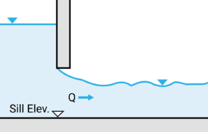
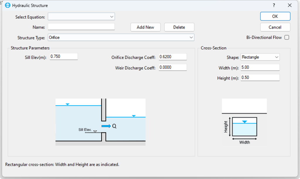
Orifice hydraulic structures are highly versatile and applicable in various environmental management practices such as flood control. They can be used to minimize flood risks by adjusting water levels, thus preventing inundation and maintaining downstream flow within acceptable limits. In the context of hydrodynamic models, an in-depth exploration of orifice operation allows engineers and scientists to fine-tune the parameters governing flow for accurate simulation and optimization of hydraulic systems, ensuring the sustainable and efficient use of water resources. The form used to assign the Orifice option is shown in Figure 3 . This option is set by clicking the Hydraulic Structures item in the menu in the External Forcing Data form. Click on the Structure Type and select the Orifice option. The Structure Parameters will then be displayed. The Sill Elevation, Orifice Discharge Coefficient (which typically ranges from 0.6 to 0.85), and Weir Discharge Coefficient (typically ranging between 0.6 and 1.0) need to be input. After that, the cross-sectional shape should be selected with the same parameters as those required in the setting form for culverts.
Sluice Gates
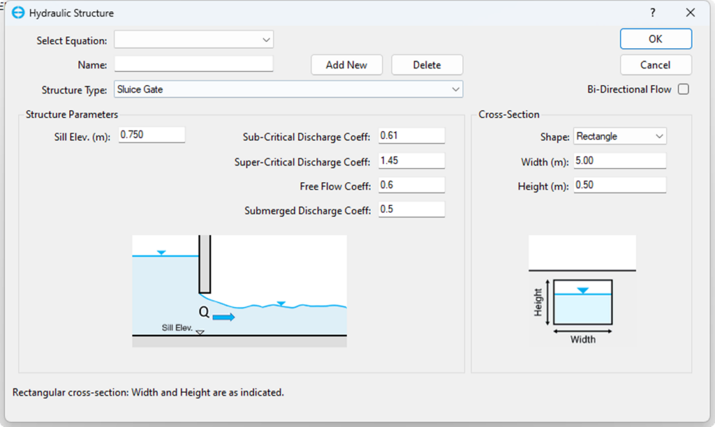
Sluice gates are crucial for controlling water flow in hydraulic systems such as rivers, canals, and reservoirs. Available in various designs, they help manage water levels, prevent floods, maintain flow rates, and protect against saline intrusion. Understanding sluice gate operation is key for predicting water flow dynamics and optimizing control strategies in hydrodynamic modeling. In order to configure a sluice gate in EEMS, input parameters are required, including sill elevation, sub-critical and super-critical discharge coefficients, free flow coefficient, and submerged discharge coefficient, as shown in Figure 4. These coefficients vary based on gate design, water properties, and specific conditions. Typically, sub-critical and super-critical discharge coefficients range from 0.6 to 1.2, free flow coefficient around 1.0, and submerged discharge coefficient from 0.5 to 1.0. The process for selecting the cross-sectional shape is similar to that for configuring culverts.
Sharp Crested Weirs
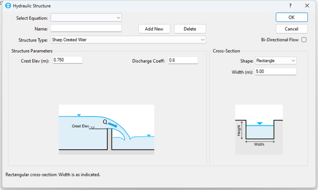
A sharp-crested weir is commonly used in hydrodynamic models to measure and control water flow. It typically features a V-shaped crest that allows water to flow over it, enabling the quantification of discharge velocity. In hydrodynamic models of various situations, such as rivers, channels, and reservoirs, this structure is used to support flood risk assessment, manage water resources, and assist the design of hydraulic systems. The configuration form used to assign the Sharp Crested Weir option is shown in Figure 4, which is the same process as the Culverts and Orifice options mentioned earlier. The crest elevation and discharge coefficient (typically ranging between 0.6 and 0.65) are required. The choice of the cross-sectional shape can be made using a selection process similar to that described for culverts.
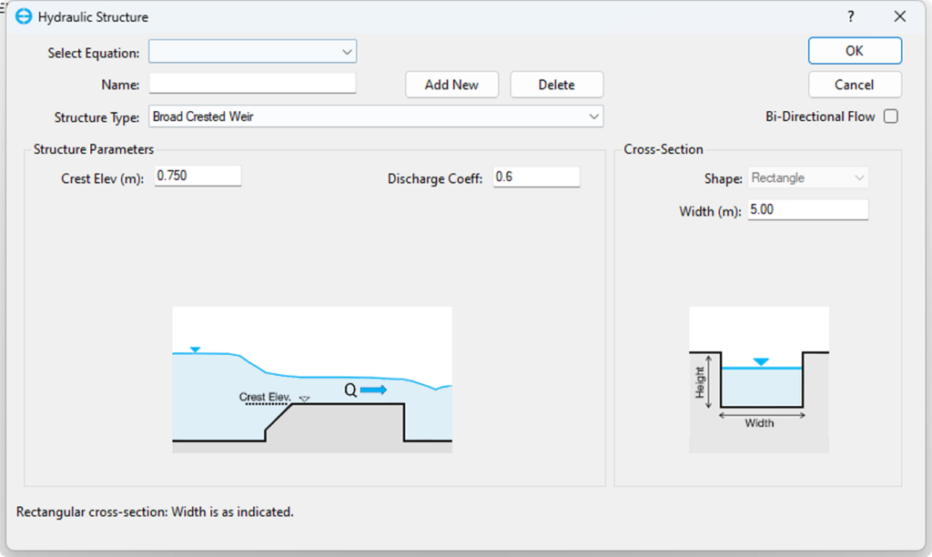
Broad Crested Weirs
This type of weir consists of a wide, flat-topped structure, typically positioned in a river. Its primary function is to control water levels. By simulating the interaction between the weir and the flowing water, hydrodynamic models assist decision-makers in making informed decisions about water infrastructure, mitigating flood risks, and assessing environmental impacts in diverse hydrological environments. The form used to assign the Broad Crested Weir option is shown in Figure 5. This option is set up using the same process as the options mentioned above, with the necessary information being crest elevation, discharge coefficient, and width.
Additionally, enabling the Bi-Directional Flow option is crucial for structures allowing bi-directional flow. In the Time Control option (Figure 1), specifying whether the structure is controlled or uncontrolled is essential, with controlled structures requiring rule tables for operation. For more information regarding controlled/uncontrolled structures, we recommend reading the Simulating Hydraulic Structures in EEMS blog.
Conclusion
By offering various equation-based flow control approaches, EEMS allows users to reflect the actual performance and behavior of complex hydraulic structures in hydrodynamic modeling. This flexibility ensures that EEMS remains a robust and versatile tool for environmental engineers and hydrologists, facilitating detailed and accurate simulations essential for effective water resource management, flood control, and environmental protection.
Do you want to try these options for yourself? There are several examples of hydraulic structure models on the EEMS website. These include a Low Chord Trapezoidal Bridge, a Culvert with Tidal Signal, and a Sluice Gate Hydraulic Structure. You can run any of these in the free demo mode of EEMS. To see these features in action, head over to our YouTube page.
Please get in touch with us if you have comments or questions. For more information on EFDC+ capabilities, contact the DSI team today.
