Anti-Reflection Open Boundary Condition
Boundary conditions are one of the key aspects of hydrodynamic models and require special attention. EFDC+ Explorer previously provided four options for open boundary conditions:
- ISPBW (0) for elevation specified, zero tangential velocity.
- ISPBW (1) for incoming wave radiation- separation condition, zero tangential velocity.
- ISPBW (2) for incoming wave radiation- separation condition, free tangential velocity.
- ISPBW (3) for elevation specified, free tangential velocity.
In EFDC+ Explorer 11 two new open boundary condition types have been added to improve the propagation of waves out of the model domain without reflecting off the open boundary. These boundaries are named anti-reflection open boundaries. Both free tangential and a zero tangential anti-reflection boundary conditions are available now in the setting.
- ISPBW (4) for outgoing wave (Anti-reflective) condition, zero tangential velocity.
- ISPBW (5) for outgoing wave (Anti-reflective) condition, free tangential velocity.
This specific boundary condition helps avoid undesirable boundary effects and improves the simulations. The boundary type can be changed in the open boundary tab, as shown in Figure 1.
In a hydrodynamic model, the zero tangential and free tangential open boundary conditions are two different approaches used to represent the behavior of water flow at the model boundaries. The selection of the appropriate condition depends on the specific characteristics and behavior of the water flow at the boundary being modeled. Here is the difference between these two conditions:
Zero Tangential: The zero tangential open boundary condition assumes that there is no tangential flow at the model boundary. It means that the water flow parallel to the boundary is considered to be zero. This condition effectively restricts any lateral flow or exchange of momentum along the boundary, assuming a no-slip condition.
Free Tangential: The free tangential open boundary condition allows for tangential flow at the model boundary. It acknowledges the presence of lateral flow or exchange of momentum parallel to the boundary. This condition is employed when there is a need to simulate water flow interacting with open boundaries.
The difference between zero and free tangential options in the EFDC+ is that in the zero tangential option, there is masking between the cells in the first two columns of cells when assigning the open boundaries, but in free tangential, the masking is only between the cells in the first column as can be seen in Figures 2 and 3. As a result, utilizing the zero tangential option leads to enhanced stability within the model.
Test case 1
A test case simulating a square channel with initial conditions of zero currents everywhere, with a free-surface bump on the left side of the channel and an east open boundary on the right end was created. The test model consists of 14 grid rows and 84 grid columns in the horizontal plane and 10 vertical layers. The channel test case here is based on the configuration described in Ni et al., (2016), and the bump is defined with the equation below:
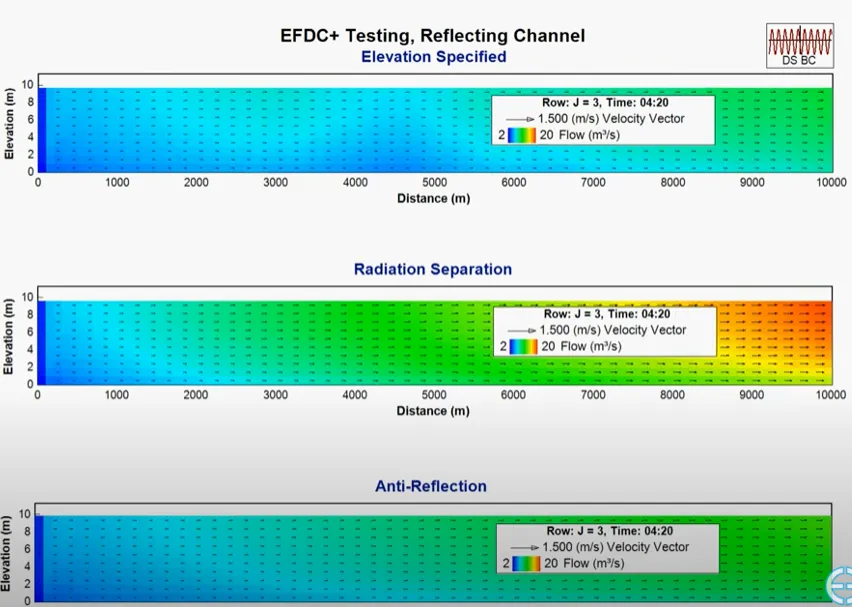
The three open boundary condition options, including ISPBW (0), ISPBW (1), and ISPBW (4) were tested on this test case model, and the velocity vector and flow using a 2DV animation of a cross-section of the model created. As can be seen from the animation (Figure 5), the specified elevation boundary option (ISPBW (0)) reflects the flow at the open boundary cells, but the radiation and Anti-reflection open boundaries (ISPBW (1), and ISPBW (4)) act more realistic and don’t reflect the flow after hitting the open boundary. Finally, the Anti-reflection boundary settles down after about 8 seconds while it takes more for the other two models to settle down. It should be noted that the animation shows 8 seconds of the model run.
Figure 5. Animation of Test case 1
Test case 2
In the second test case, a reflecting channel is simulated, where one end of the channel has a flow boundary condition while the other end is governed by an open boundary condition (Figure 6). The test model consists of one grid row and 100 grid columns in the horizontal plane, and 10 vertical layers. Figures 7 and 8 illustrate the comparison of water depth and velocity in the x direction for the three types of open boundary conditions. In the specified elevation (ISPBW (0)) case, the velocity exhibits oscillations that eventually smooth out over time. Conversely, in the radiation (ISPBW (1)) and anti-reflection (ISPBW (4)) cases, the velocity remains smooth right from the beginning of the simulation. Notably, the main distinction between radiation and anti-reflection is the presence of an overshoot in the radiation case.
The animation below (Figure 9) demonstrates the distinctions among the three open boundary conditions in the reflecting channel test case. It should be noted that the animation shows 5 hours of the model run. The displayed results in this animation pertain to the execution of the test case using 10 layers.
Figure 9. Animation of Test case 2
Do you want to try these options for yourself? You can start by downloading EEMS and activating in the free demo mode and the running our demonstration model. To see these features in action, head over to our YouTube page.
Please contact us if you have comments or questions. For more information on EFDC+ capabilities, contact the DSI team today.
References:
Ni, X., Sheng, J., & Feng, W. (2016). Simulation of free-surface flow using the smoothed particle hydrodynamics (SPH) method with radiation open boundary conditions. Journal of Atmospheric and Oceanic Technology, 33(11), 2435–2460. https://doi.org/10.1175/JTECH-D-15-0179.1